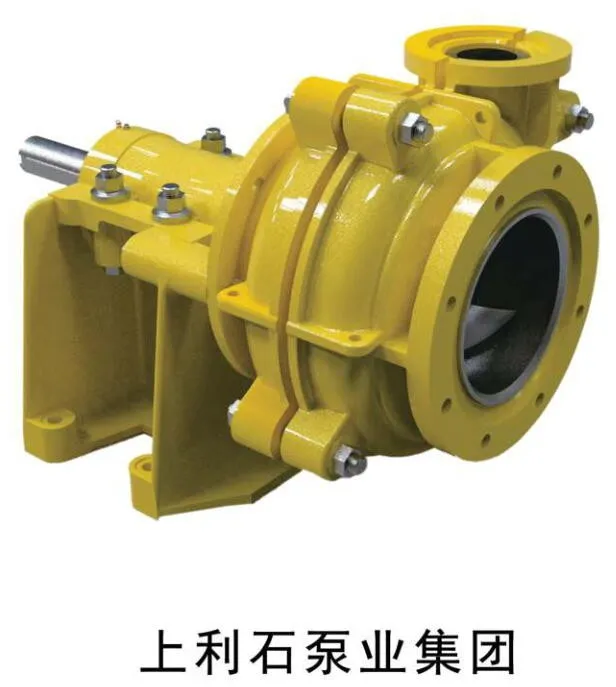
SAHFR Froth Pump
SAHFR froth pumps are for frothy slurry duties where selected lining or material configurations may be required.
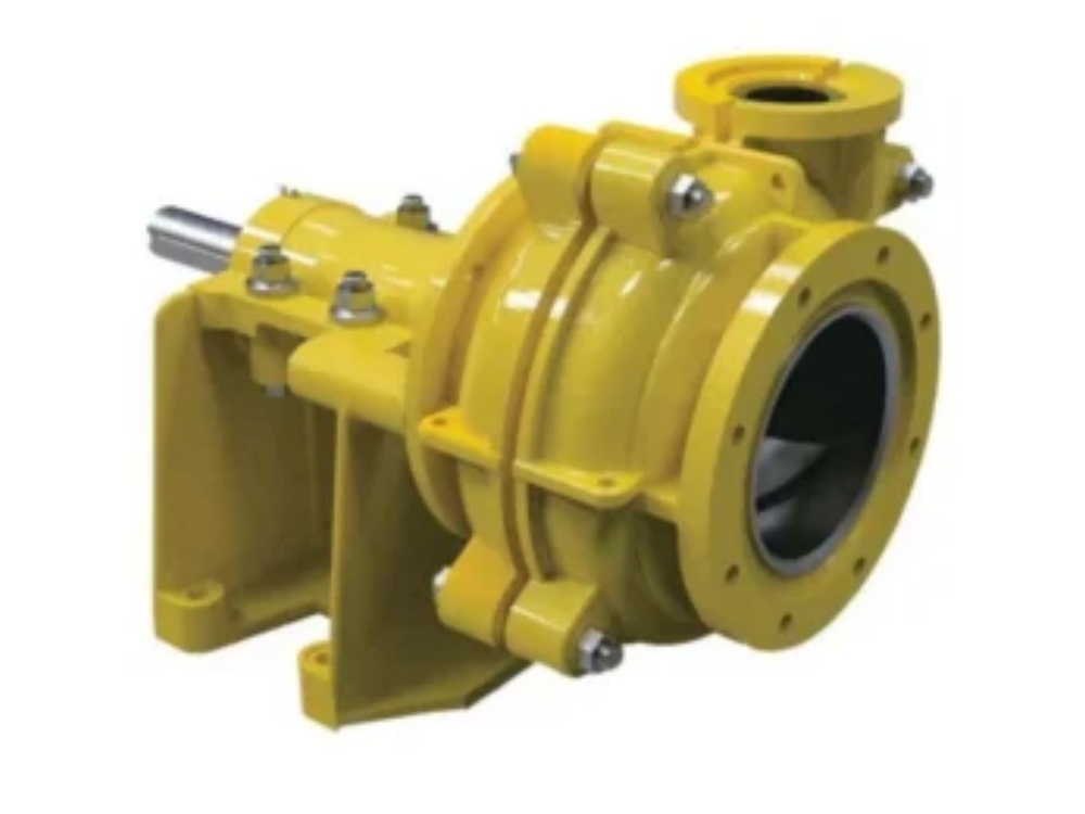
SAHFR froth pump — for frothy slurry duties where selected lining or material configurations may be required.
- Brittle froth FVF 1.1–1.25; medium 1.25–1.5; tenacious 1.5–1.8
- Pump must pass Qf = FVF × Qs, not the airless slurry flow
- No suction line and no suction lift — froth reaches the impeller under its own head
- Semi-open impeller; no shaft seal below liquid level and no seal water
- Extended-column builds for deeper hoppers, guide bearing requires flushing water
- For tenacious froth the horizontal arrangement is generally the better answer
CE · EAC · ISO 9001 · ISO 14001 · ISO 45001
Overview
SAHFR froth pumps are for frothy slurry duties where selected lining or material configurations may be required. Froth slurry contains liquid, solids and air bubbles at the same time. Froth pumps help improve feeding, deaeration and stable transfer in flotation-related slurry systems.
Selection by Froth Type
| Froth type | Froth Volume Factor (FVF) |
|---|---|
| Brittle froth | 1.1 – 1.25 |
| Medium froth | 1.25 – 1.5 |
| Tenacious froth | 1.5 – 1.8 |
The Froth Volume Factor is the ratio of froth volume to airless slurry volume, and it determines the flow the pump must pass: Qf = FVF × Qs. Selecting on the airless slurry flow is the most common error in froth applications, and it produces a pump one or two sizes too small.
Selection Procedure
| Step | Action |
|---|---|
| 1 | Determine the froth type and select the Froth Volume Factor: brittle 1.1–1.25, medium 1.25–1.5, tenacious 1.5–1.8. |
| 2 | Establish Qs, the airless slurry flow in L/s. Use the design flow, then check the selection again at the maximum slurry flow. |
| 3 | Calculate the froth flow: Qf = FVF × Qs (L/s). |
| 4 | Calculate Hs, the slurry head in metres at Qf, for the solids concentration in the slurry and disregarding the froth. Keep discharge pipe diameters large, pipe velocity below 2–2.5 m/s and static head low, so that total head stays below 35 m. |
| 5 | Convert to water head: Hw = Hs / HRf, where HRf is the head reduction factor for the froth. |
| 6 | Select a pump so that the froth duty point falls to the left of the best-efficiency line but not below 25 % of Qbep, and so that NPSH required is below 3.5 m. If in doubt, take the next larger size. Add the froth system curve to the pump curve to establish the working range. |
| 7 | At the froth duty point read the pump speed Nf and the water efficiency Ew, then calculate froth efficiency Ef = Ew × ERf. |
| 8 | Calculate the froth specific gravity from the airless slurry SG and the FVF. |
| 9 | Calculate absorbed power from froth flow, froth head, froth specific gravity and froth efficiency. |
| 10 | Confirm the drive arrangement and the speed control method, and check that the selection is not relying on over-speeding. |
Operating Rules
- Do not over-speed. Raising speed when the pump appears not to cope produces unsteady flow and oscillating discharge pressure. Reduce speed and review the selection instead.
- Minimise head. Keep total head below 35 m and pipe velocity below 2–2.5 m/s.
- Watch the hopper. A froth hopper overflowing continuously indicates the pump is not coping. Spillage should not be tolerated, because the froth carries the mineral product.
- Keep NPSHr below 3.5 m at the froth duty point and place the duty point left of best efficiency, above 25 % of Qbep.
Typical Applications
- Flotation concentrate and tailings froth transfer between stages.
- Cleaner and recleaner circuit froth handling.
- Coal preparation flotation froth.
- Froth hoppers and launder sumps in mineral processing.
Selection
Send the airless slurry flow and solids concentration, the froth character, the hopper depth from mounting plate to working level, the static head and discharge line details. We will confirm which froth pump suits the froth, and issue the selection with the froth system curve.
Send Your Enquiry
Why not select on the slurry flow?
Because froth occupies more volume than the slurry it contains. The pump must pass Qf = FVF × Qs, which for tenacious froth is up to 1.8 times the airless flow.
What if the froth hopper keeps overflowing?
It indicates the pump is not coping. Check the FVF used in the selection and the inlet arrangement — do not raise the speed.
Manufacturer-direct supply · Technical pump-selection support · Export documentation on request.