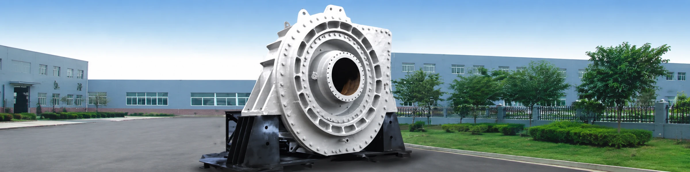
WN Dredge Pump — Cutter-Suction, Submerged & Hydraulic Dredging
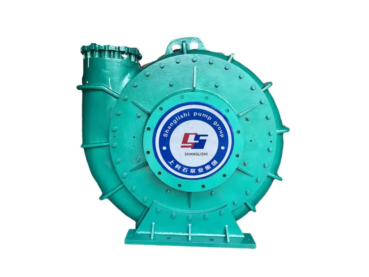
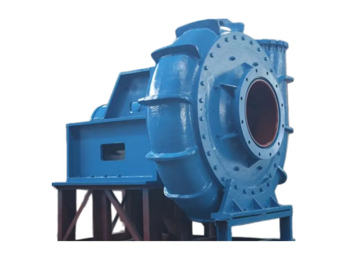
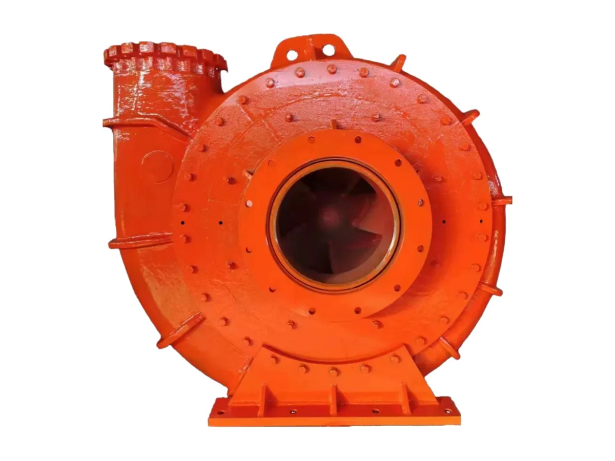
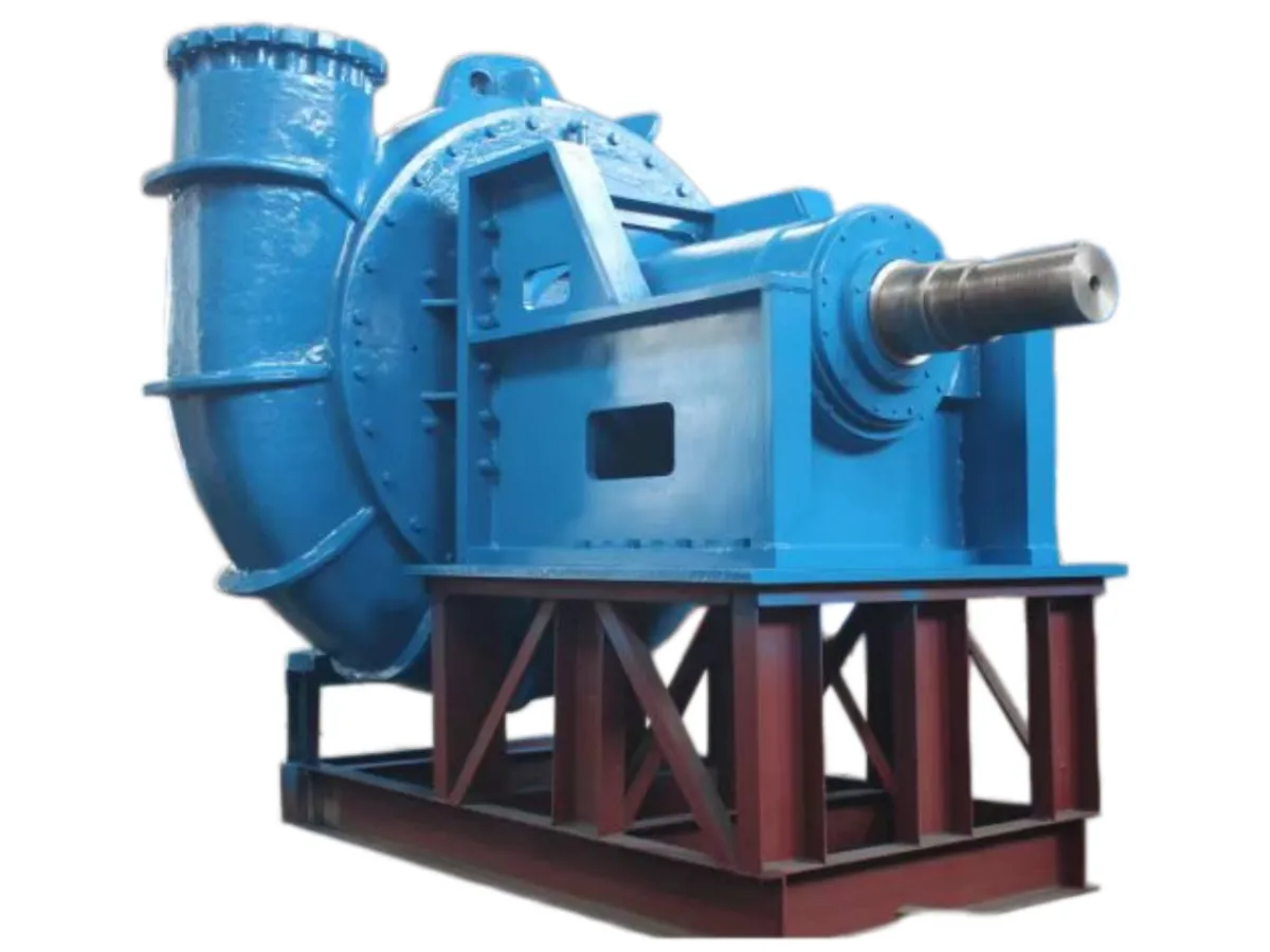
Hydraulic dredge pump — duty is defined by the largest solid arriving at the inlet and the mixture concentration, both set by the dredging process. Selection starts with the material, not the duty point.
- Single-casing construction — no liner to break on coarse gravel
- Full wall thickness serves as wear material
- Discharge rotatable to any orientation for dredge and pontoon pipework
- A22 (1200 MPa, HRC45) for casings; A23 for components
- A25 (HB300–350) weldable — permits on-vessel repair of large castings
- Every model has a stated maximum particle diameter — select on that first
CE · EAC · ISO 9001 · ISO 14001 · ISO 45001
Overview
A hydraulic dredge pump moves material that has been cut or loosened at the bed and delivered to the suction as a coarse, dense slurry. The duty is defined by two things the pump has little control over: the largest solid arriving at the inlet, and the concentration of the mixture. Both are set by the dredging process, which is why dredge pump selection starts with the material rather than with the duty point.
Single-Casing Construction
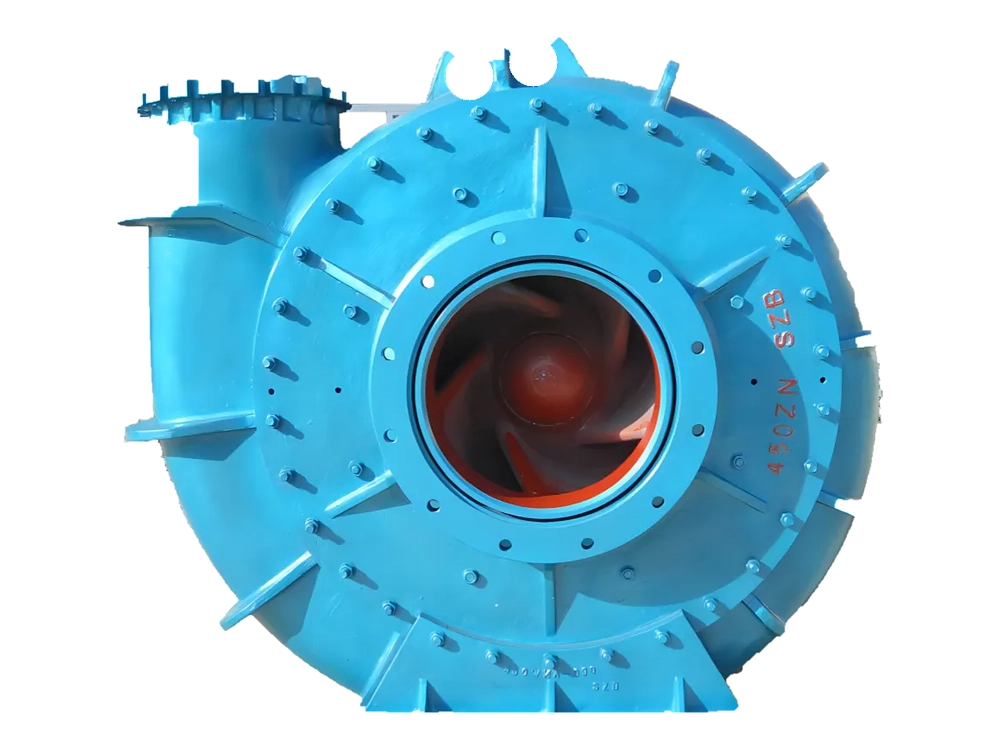
Dredge and gravel pumps are built single-casing — there is no replaceable liner. Pump body, cover and impeller are all cast in wear-resistant metal, so the full wall thickness serves as wear material. On coarse gravel duty a liner would be broken rather than worn, and the load would then be carried by an outer shell never intended to take it. Body and cover are joined by a clamping arrangement, and the discharge can be rotated to any orientation — on a dredge or a mobile pontoon where the discharge line geometry is fixed by the vessel, that adjustment is what makes installation practical.
The inlet is horizontal and the pump rotates clockwise viewed from the drive end.
Wear Materials for Dredge Duty
Two grades in our material system are specified for dredge service in particular:
| Grade | Tensile (MPa) | Hardness | Application |
|---|---|---|---|
| A22 | 1200 | HRC45 | Good erosion resistance with higher hardness — specified for dredge pump casings |
| A23 | 700 | HB500–600 | Higher hardness with fair erosion resistance — dredge pump components, and slurry and sewage pump parts in high-erosion duty |
| A05 | ≥700 | ≥HRC62 | High-chrome white iron for high-impact abrasive wear at pH 5–12 |
| A25 | — | HB300–350 | Lower hardness, weldable — allows on-site repair of large castings |
A25 deserves a note: on large dredge castings the ability to weld-repair in place is sometimes worth more than the last increment of hardness, because a casting that can be repaired on the vessel does not become a lost season.
Range Coverage
Fourteen frame sizes are listed in the table below, covering 600-25,000 l/s at 20-85 m of head, running between 181 and 900 r/min. Suction branches run 250-1,200 mm and discharge branches 200-1,000 mm. Best-efficiency values rise from around 60% on the smallest frames to 85-87% on the largest, and required NPSH stays below 6 m across the range. Maximum passing particle size runs from 144 mm to 354 mm depending on frame.
Model Performance Data
Clear-water performance across the WN range. Ratings are per frame size; the D suffix denotes the lower-head build.
| Model | Capacity (l/s) | Head (m) | Speed (r/min) | Efficiency (%) | NPSHr (m) | Inlet dia. (mm) | Outlet dia. (mm) | Max particle (mm) |
|---|---|---|---|---|---|---|---|---|
| 200WND | 600–800 | 20–40 | 700–900 | 60–65 | <4.5 | 250 | 200 | 178 |
| 200WN | 750–1000 | 40–65 | 700–850 | 70–72 | <4 | 250 | 200 | 180 |
| 250WND | 950–1100 | 20–40 | 500–700 | 65–70 | <4 | 300 | 250 | 220 |
| 250WN | 1100–1300 | 40–65 | 500–650 | 70–74 | <4 | 350 | 250 | 144 |
| 300WDN | 1500–1800 | 20–40 | 400–600 | 65–68 | <4 | 350 | 300 | 241 |
| 300WN | 1800–2200 | 40–65 | 400–550 | 74–78 | <4 | 450 | 300 | 241 |
| 350WN | 2600–3000 | 40–65 | 400–550 | 74–78 | <4.5 | 450 | 350 | 245 |
| 400WN | 2800–3200 | 20–40 | 400–550 | 74–78 | <4.5 | 450 | 400 | 250 |
| 450WN | 3200–3850 | 40–67 | 350–500 | 76–80 | <4.5 | 600 | 450 | 354 |
| 500WND | 3600–4200 | 20–40 | 220–320 | 72–75 | <4.8 | 600 | 500 | 330 |
| 500WN | 4500–5500 | 40–65 | 350–450 | 78–80 | <4.8 | 650 | 500 | 250 |
| 600WN | 5000–9000 | 55–80 | 280–420 | 81–85 | <6 | 660 | 600 | 220 |
| 700WN | 8000–12000 | 60–85 | 280–380 | 83–85 | <6 | 760 | 700 | 280 |
| 900WN | 12000–19000 | 50–75 | 280–330 | 85–87 | <6 | 960 | 900 | 320 |
| 1000WN | 16000–25000 | 23–76 | 181–290 | 85–87 | <6 | 1200 | 1000 | 350 |
Additional sizes are available on request.
Selecting a Frame
Choose on discharge duty first, then check that the largest expected spoil will pass the frame you have picked, since particle size rather than flow is usually what rules a dredge frame in or out. Note that capacity is quoted in litres per second here, matching the source data; convert before comparing against pumps rated in cubic metres per hour. Send the cutter or bucket-wheel type, dig depth, discharge distance and spoil grading and we will confirm the frame and drive arrangement.
Selecting by Particle Size
Dredge duty is set by the largest solid, not the average. Every model has a stated maximum particle diameter, and the pump must be selected so that the largest stone actually reaching the suction will pass. Selecting on flow and head and leaving particle size to chance is the most common cause of blockage in this service — and a blockage on a dredge is a shift lost, not a maintenance item.
Suction Conditions
Keep the suction line short and direct, keep velocity high enough to hold solids in suspension but not so high that wear accelerates, and avoid high points where air can collect. Where the dredge draws down and the suction can break, arrange for the pump to be primed rather than relying on it to recover.
On Cutter-Suction Craft
- Start with the material. Establish the largest solid the cutter will pass to the suction, and select so that solid will go through the pump.
- Then the mixture. Set the design concentration and the density that follows from it; the head the pump has to generate scales with mixture density.
- Then the pipeline. Calculate the discharge line loss at the design velocity for the full line length, including the floating section, and keep velocity above the settling limit for the coarsest fraction.
- Then the duty point. Only now does the flow and head pair become meaningful, and it should be checked at both the shortest and the longest line configuration the job will use.
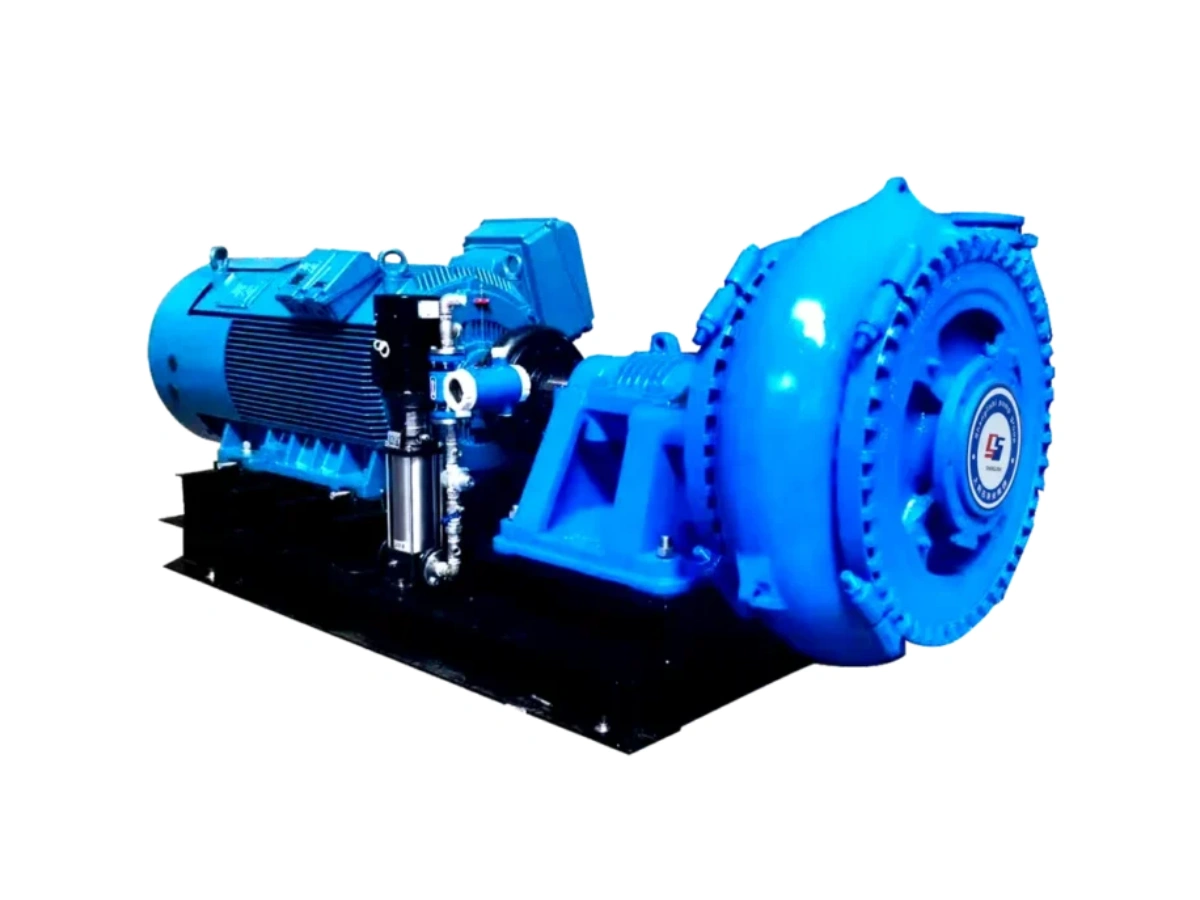
- Confirm the drive. Speed control matters on this duty because concentration varies; confirm the available speed range with the selection.
Operating Notes
- Keep the suction line short and direct, and avoid high points where air can collect.
- Hold pipeline velocity above the settling limit for the coarsest particles; a settled line is harder to clear than a blocked pump.
- Where the suction can break as the ladder lifts, arrange priming rather than relying on the pump to recover.
- Monitor discharge pressure — a falling pressure at unchanged speed and concentration indicates wear at the impeller and casing.
Submerged & Amphibious Deployment
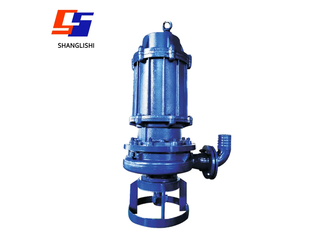
- Submerged operation — the pump works at significant depth, taking material directly at the bed for underwater dredging and excavation.
- Stable suction — the pump is always flooded, so suction conditions do not vary with level and cavitation risk is reduced.
- High solids concentration — the unit sustains solids loadings that starve a surface-mounted pump drawing through a suction line.
- Motor cooling by the medium — pumped liquid passes around the outer sleeve of the motor, so cooling improves with submergence and the motor stays sealed against ingress.
Getting the Pump to the Face
Mobile hose installation suits dredging work directly: the pump is supported on its base with a hose connector to the discharge line, so it can be repositioned along a channel or moved between pits without fixed civil work. Mobile hard-pipe installation is used where the discharge run is fixed. For permanent installations, fixed wet mounting on a base at the bed, or fixed dry mounting with flanged connections and a cooling system, are both available.
Wear Parts and Rebuilds
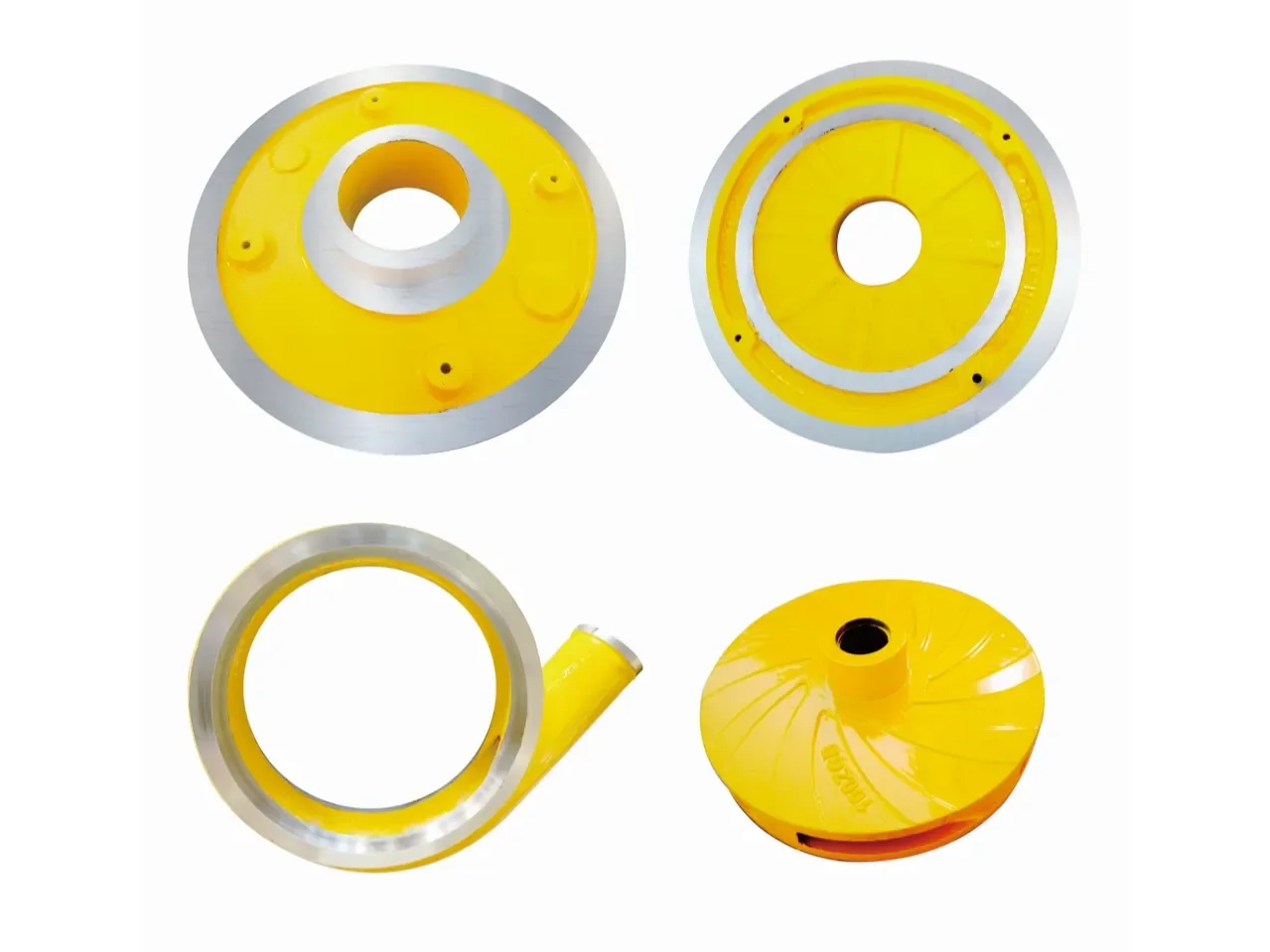
Impellers, volute liners, throatbushes, frame and cover plate liners, expeller rings and shaft sleeves are all supplied separately, in high-chrome alloy, ceramic, polyurethane or rubber, so a worn dredge pump can be rebuilt rather than replaced. Parts can be matched from your sample or drawing; dimensions and tolerances are confirmed on request.
Typical Applications
- River, lake and reservoir dredging and desilting.
- Harbour and navigation channel maintenance.
- River sand extraction and sand recovery.
- Mining vessel and dredge pontoon duty.
- Tailings and coarse mineral transport.
- Municipal engineering and land reclamation fill.
Selection
Send the largest particle size reaching the suction, the solids concentration and mixture density, the required flow and total head including the discharge line, the drive arrangement and available speed, and the suction geometry. We will confirm the model and the wear material. Model-by-model performance data and dimension drawings are issued with the quotation.
Send Your Enquiry
Dredge Pump for Sand Dredging OperationsDredge Pump Rental & Distributor ProgramGold Dredge Pump for Placer & Alluvial Mining How Does a Dredge Pump Work? A Practical Guide
Why is there no replaceable liner?
On coarse gravel and dredge duty a liner is broken rather than worn. Single-casing construction puts the full wall thickness in wear-resistant metal so there is no thin liner to fail.
Which material for the casing?
A22 anti-wear cast steel, 1200 MPa, HRC45, is specified for dredge pump casings. A23 is used for components, and A25 where weld repair capability matters more than hardness.
What decides the model?
The largest solid reaching the suction, before flow and head. A pump selected on duty point alone will block on the first oversize stone.
Can the discharge orientation be set on site?
Yes. Body and cover are joined by a clamping arrangement and the discharge rotates to any orientation, which matters where the discharge geometry is fixed by the vessel.
Do you publish model-by-model performance data?
It is issued with the quotation together with the dimension drawing. Send us the duty and the material and we will return the selection.
Manufacturer-direct supply · Technical pump-selection support · Export documentation on request.