

SAHF Froth Pump — Open-Impeller Froth Service
The SAHF froth pump is a froth-service variant of our horizontal slurry pump range, built with an open froth impeller, enlarged-bore throatbush and new cover plate; horizontal is preferred for less floor space, easier maintenance and higher froth flow.
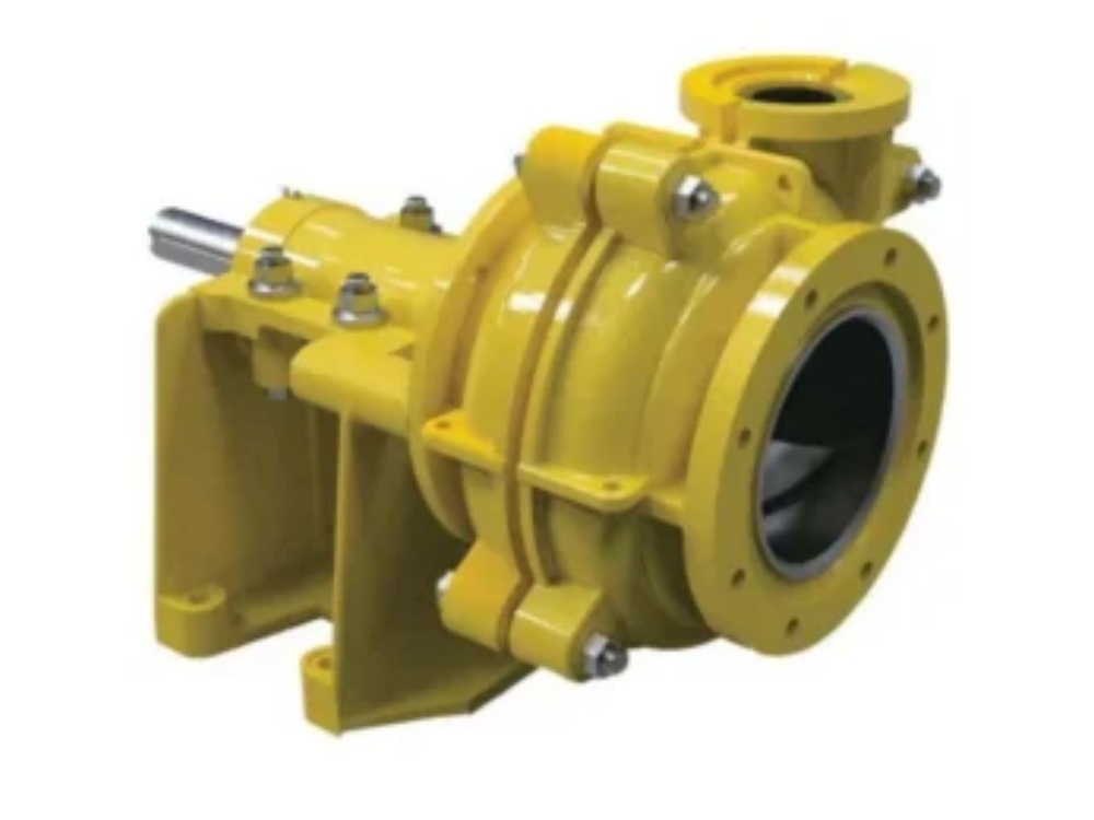
Horizontal froth pump — froth is not slurry with air in it as far as a pump is concerned. Air in the impeller eye is the condition a centrifugal pump handles worst, and most froth problems come from application and operation rather than the pump.
- Froth Volume Factor sets the flow: Qf = FVF × Qs, up to 1.8× the airless flow
- Enlarged inlet and flow inducer raise available NPSH for tenacious froth
- Open impeller induces swirl at the intake to break out air
- Keep total head below 35 m, pipe velocity below 2–2.5 m/s, NPSHr below 3.5 m
- Duty point left of best efficiency but above 25 % of Qbep
- Never raise speed to compensate — over-speeding destroys froth performance
CE · EAC · ISO 9001 · ISO 14001 · ISO 45001
Why Froth Needs a Different Pump
Froth is not slurry with air in it as far as a pump is concerned. In a flotation circuit, fine mineral particles attach to air bubbles and float; the froth that spills from the cell lip carries the mineral product and has to be moved to the next stage. Air in the impeller eye is exactly the condition a centrifugal pump handles worst — it accumulates, the pump loses prime, and the duty becomes unsteady. Most froth pumping problems trace to incorrect application and incorrect operation rather than to the pump itself.
The SAHF froth pump is built around that problem. Modifications are concentrated at the inlet, where the difficulty starts, so the pump remains a conventional horizontal unit for maintenance purposes while handling froth at the suction.
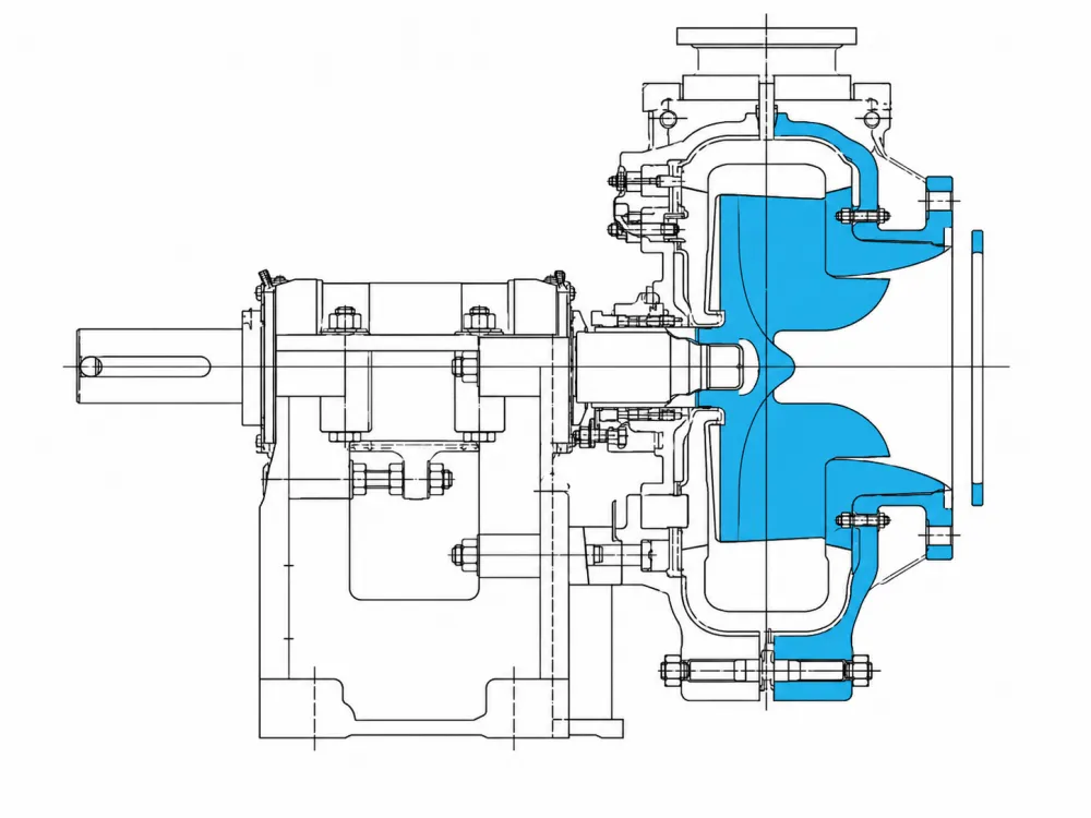
Inlet Design
- Enlarged inlet — for tenacious froths the pump inlet size is increased so the froth can enter without being throttled.
- Flow inducer in the intake — adds energy ahead of the impeller and raises the NPSH available, which is the quantity that limits froth pumping.
- Open impeller — the open form is the most effective at inducing swirl in the froth slurry at the intake, which helps break the air out before the impeller eye.
Froth Pump Selection Procedure
Froth cannot be selected on flow and head alone. The froth occupies more volume than the slurry it contains, and that ratio — the Froth Volume Factor — sets the flow the pump actually has to pass.
| Froth type | Froth Volume Factor (FVF) |
|---|---|
| Brittle froth | 1.1 – 1.25 |
| Medium froth | 1.25 – 1.5 |
| Tenacious froth | 1.5 – 1.8 |
| Step | Action |
|---|---|
| 1 | Determine the froth type and select the Froth Volume Factor: brittle 1.1–1.25, medium 1.25–1.5, tenacious 1.5–1.8. |
| 2 | Establish Qs, the airless slurry flow in L/s. Use the design flow, then check the selection again at the maximum slurry flow. |
| 3 | Calculate the froth flow: Qf = FVF × Qs (L/s). |
| 4 | Calculate Hs, the slurry head in metres at Qf, for the solids concentration in the slurry and disregarding the froth. Keep discharge pipe diameters large, pipe velocity below 2–2.5 m/s and static head low, so that total head stays below 35 m. |
| 5 | Convert to water head: Hw = Hs / HRf, where HRf is the head reduction factor for the froth. |
| 6 | Select a pump so that the froth duty point falls to the left of the best-efficiency line but not below 25 % of Qbep, and so that NPSH required is below 3.5 m. If in doubt, take the next larger size. Add the froth system curve to the pump curve to establish the working range. |
| 7 | At the froth duty point read the pump speed Nf and the water efficiency Ew, then calculate froth efficiency Ef = Ew × ERf. |
| 8 | Calculate the froth specific gravity from the airless slurry SG and the FVF. |
| 9 | Calculate absorbed power from froth flow, froth head, froth specific gravity and froth efficiency. |
| 10 | Confirm the drive arrangement and the speed control method, and check that the selection is not relying on over-speeding. |
The Single Most Common Mistake
Over-speeding. When a froth pump appears not to be coping, the instinct is to raise the speed. In froth duty that is the worst available response: it produces unsteady flow and oscillating discharge pressure, and it destroys performance rather than recovering it. The correct action is normally to reduce speed, and to check the inlet arrangement and the selection instead.
A related indicator is worth watching on site: a feed hopper that overflows continuously is a reliable sign that the froth pump is not coping. Spillage should not be tolerated, because the froth carries the mineral product.
Rules of Thumb
- Select the correct pump size for the froth type — not the size that matches the airless flow.
- Minimise the head. Keep total head below 35 m where possible.
- Keep discharge pipe diameters large and pipe velocity below 2–2.5 m/s.
- Keep NPSH required below 3.5 m at the froth duty point.
- Place the froth duty point left of best efficiency, but not below 25 % of Qbep.
- Where the selection is marginal, take the next larger pump.
Other Difficult Slurries
Because the inlet modifications address entry rather than the impeller passage, the SAHF froth pump also performs well on other media that are hard to get into a pump — higher-viscosity non-Newtonian slurries and viscous froths with a yield stress. Once a difficult slurry has entered the impeller it is generally pumped successfully; the inlet is where the selection is won or lost.
Selection
Send the airless slurry flow and solids concentration, the froth type (brittle, medium or tenacious) or the measured Froth Volume Factor, the static head and discharge line details, and the available NPSH at the pump inlet. We will work the selection procedure above and issue the pump and impeller selection with the froth system curve.
Send Your Enquiry
What is the Froth Volume Factor?
The ratio of froth volume to airless slurry volume. It sets the flow the pump must actually pass: Qf = FVF × Qs. Brittle froths are 1.1–1.25, medium 1.25–1.5 and tenacious 1.5–1.8.
The pump is not keeping up — should we increase the speed?
No. Over-speeding is the most damaging response in froth duty; it causes unsteady flow and oscillating discharge pressure. Reduce speed and review the inlet arrangement and the selection.
What NPSH should we design for?
Keep NPSH required below 3.5 m at the froth duty point, and keep total head below 35 m with pipe velocity below 2–2.5 m/s.
Where should the duty point sit on the curve?
To the left of the best-efficiency line, but not below 25 % of best-efficiency flow. If the selection is marginal, take the next larger pump.
Can the pump handle non-Newtonian viscous slurry?
Yes. The inlet modifications that suit froth also suit viscous non-Newtonian slurries with a yield stress, which are difficult to get into a pump rather than difficult to pass through it.
Manufacturer-direct supply · Technical pump-selection support · Export documentation on request.

