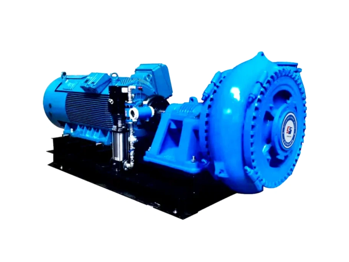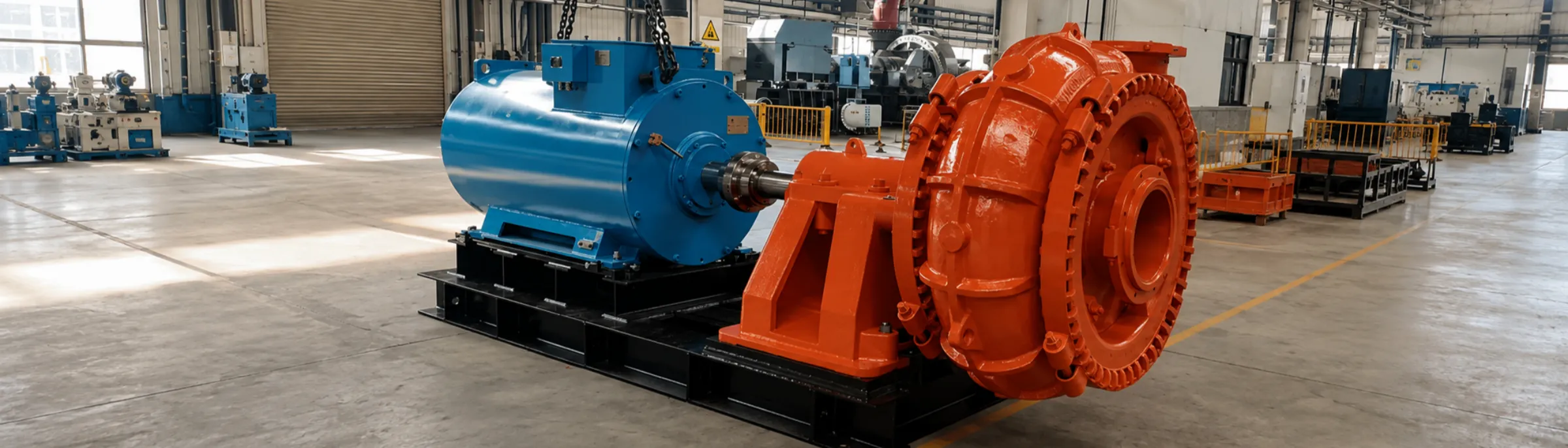
High-Head Gravel Sand Pump — SGH Series
The SGH is the high-head variant of the gravel-pump range for greater lift at large particle size; part of the 36–4320 m³/h / 5–80 m / 60–1200 kW SG/SGH family, particle to 254 mm.
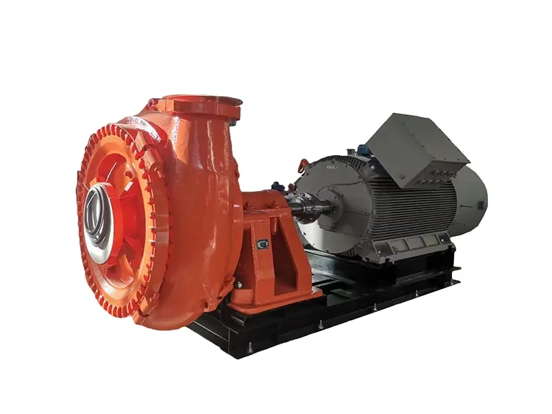
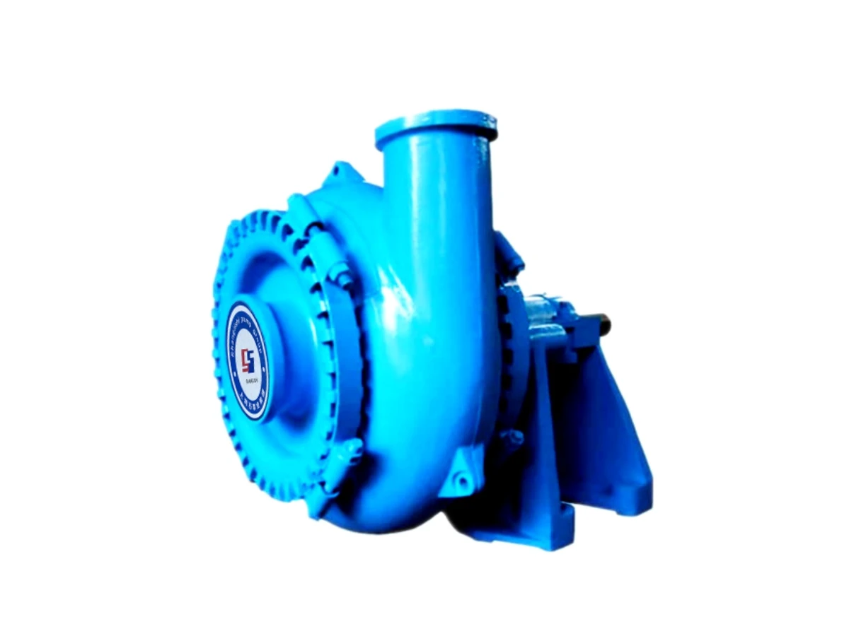
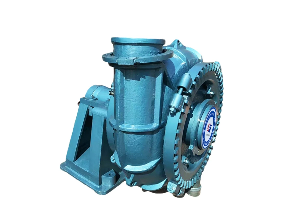
Continuous duty on coarse gravel, sand and tailings — the high-head build of our SG gravel pump range, for long discharge lines and high lift where the medium still carries large solids.
- Three SGH sizes: 110–1000 L/s at 18–80 m head
- Maximum particle 180–230 mm; SG range to 254 mm
- Single-casing construction — no liner to break on coarse gravel
- Discharge rotatable to any orientation
- Wear materials A05 / A22 / A23 / A25 to duty
CE · EAC · ISO 9001 · ISO 14001 · ISO 45001
Overview
The SGH gravel pump is the high-head variant of the SG series. Where the SG models cover heads to about 66 m, the SGH models reach 78–80 m at the same solids-handling capability, which makes them the selection when the discharge line is long or the lift is high and the medium still carries coarse gravel.
Three SGH sizes are built: 10/8S-SGH, 12/10T-SGH and 16/14TU-SGH, covering 110–1000 L/s at 18–80 m head with maximum particle sizes of 180–230 mm.
Where the SGH Fits
- 10/8S-SGH — 110–360 L/s, 18–80 m, 500–950 r/min, 250/200 mm connections, particles to 180 mm. The highest head in the range.
- 12/10T-SGH — 170–620 L/s, 28–78 m, 350–700 r/min, 300/250 mm connections, particles to 210 mm. The widest usable head band with a high minimum head.
- 16/14TU-SGH — 200–1000 L/s, 20–72 m, 300–500 r/min, 400/350 mm connections, particles to 230 mm. The high-volume selection.
Efficiency across the three SGH sizes is quoted at 60–72 %, and NPSHr at 2–8 m depending on model and duty point.
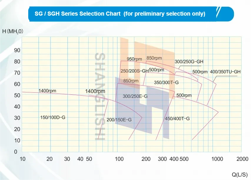
Selecting Against Particle Size
Gravel duty is set by the largest solid, not by the average. Each model has a stated maximum particle diameter — 82 mm on the smallest through 254 mm on the largest SG size — and the pump must be selected so that the largest stone actually present will pass. Selecting on flow and head alone and ignoring particle size is the most common cause of blockage in this service.
Typical Applications
- Coal preparation and coal gravel transfer
- Power station gravel and ash handling
- River dredging and desilting
- River sand extraction and mining vessels
- Municipal engineering and material transport
- Mine tailings and coarse mineral transfer
- Land reclamation and fill placement
- Quarry and wash-plant duty
Installation Dimensions
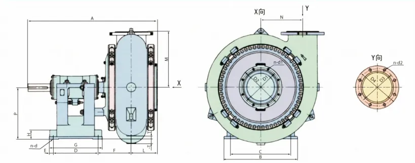
Drawing annotations
- Pump weight — total mass of the bare pump
- Discharge flange — outlet flange dimensions
- Intake flange — inlet flange dimensions
- Head dimensions — wet-end envelope
- H.D. bolt holes — holding-down bolt pattern
- Base dimensions — baseplate footprint
- View X / View Y — sectional view directions marked on the drawing
The dimension drawing is reproduced from the manufacturer technical documentation; annotation labels are translated above.
Selection
Send the required flow and head, the largest particle size present, the solids concentration and the density of the medium, together with the drive arrangement and available speed. We will confirm the model from the tables above and issue the matching performance curve and certified dimension drawing.
Send Your Enquiry
Performance data — SG and SGH series
| Model | Capacity (L/s) | Head (m) | Speed (r/min) | Efficiency (%) | NPSHr (m) | Inlet dia. (mm) | Outlet dia. (mm) | Max. particle (mm) |
|---|---|---|---|---|---|---|---|---|
| 6/4D-SG | 10-70 | 3.5-51 | 600-1400 | 30-50 | 2.5-3.5 | 150 | 100 | 82 |
| 8/6E-SG | 38-160 | 10-48 | 800-1400 | 50-60 | 3-4.5 | 200 | 150 | 127 |
| 10/8S-SG | 60-272 | 13-50 | 500-1000 | 45-65 | 3-7.5 | 250 | 200 | 178 |
| 10/8F-SG | 60-272 | 13-50 | 500-1000 | 45-65 | 3-7.5 | 250 | 200 | 178 |
| 12/10F-SG | 100-420 | 11-58 | 400-850 | 50-70 | 2-4.5 | 300 | 250 | 220 |
| 12/10G-SG | 100-420 | 11-58 | 400-850 | 50-70 | 2-4.5 | 300 | 250 | 220 |
| 14/12G-SG | 140-880 | 6-66 | 300-700 | 60-68 | 2-8 | 350 | 300 | 241 |
| 18/16G-SG | 240-1060 | 9-48 | 250-500 | 60-72 | 3-6 | 450 | 400 | 254 |
| 18/16T-SG | 240-1060 | 9-48 | 250-500 | 60-72 | 3-6 | 450 | 400 | 254 |
| 10/8S-SGH | 110-360 | 18-80 | 500-950 | 60-72 | 2-5 | 250 | 200 | 180 |
| 12/10T-SGH | 170-620 | 28-78 | 350-700 | 60-72 | 2-8 | 300 | 250 | 210 |
| 16/14TU-SGH | 200-1000 | 20-72 | 300-500 | 60-72 | 3-6 | 400 | 350 | 230 |
For preliminary selection only. Model-by-model performance curves are issued with the quotation.
Overall dimensions and weight (mm / kg)
| Model | A | B | C | D | E | F | G | Weight (kg) |
|---|---|---|---|---|---|---|---|---|
| 6/4D-SG | 1006 | 492 | 432 | 213 | 38 | 330 | 289 | 460 |
| 8/6E-SG | 1286 | 622 | 546 | 257 | 54 | 392 | 365 | 1120 |
| 10/8F-SG | 1591 | 857 | 762 | 349 | 45 | 487 | 540 | 2250 |
| 12/10F-SG | 1702 | 883 | 762 | 584 | 60 | 411 | 705 | 3320 |
| 10/8S-SG | 1720 | 920 | 760 | 640 | 70 | 378 | 780 | 2285 |
| 12/10G-SG | 2010 | 1207 | 851 | 749 | 64 | 473 | 876 | 4450 |
| 14/12G-SG | 2096 | 1207 | 851 | 749 | 64 | 502 | 876 | 5400 |
| 18/16G-SG | 2111 | 1207 | 851 | 749 | 64 | 503 | 876 | 6950 |
| 18/16T-SG | 2607 | 1397 | 1194 | 921 | 102 | 703 | 1124 | 8850 |
| 10/8S-SGH | 1774 | 920 | 760 | 640 | 70 | 455 | 780 | 3188 |
| 16/14TU-SGH | 2375 | 1480 | 1200 | 860 | 95 | 649 | 1050 | † |
Installation and flange dimensions (mm)
| Model | H | L | M | N | P | T | N-d | D1 | D2 | n-d1 | D3 | D4 | n-d2 |
|---|---|---|---|---|---|---|---|---|---|---|---|---|---|
| 6/4D-SG | 54 | 203 | 343 | 260 | 330 | 16 | 4-Φ22 | 260 | 305 | 8-Φ19 | 210 | 254 | 4-Φ19 |
| 8/6E-SG | 75 | 295 | 405 | 352 | 457 | 54 | 4-Φ29 | 324 | 368 | 8-Φ19 | 260 | 305 | 8-Φ19 |
| 10/8F-SG | 98 | 330 | 533 | 416 | 610 | 60 | 4-Φ35 | 406 | 457 | 8-Φ22 | 324 | 368 | 8-Φ19 |
| 12/10F-SG | 98 | 368 | 667 | 522 | 610 | — | 4-Φ35 | 470 | 527 | 12-Φ22 | 406 | 457 | 8-Φ22 |
| 10/8S-SG | 90 | 330 | 533 | 416 | 450 | — | 4-Φ35 | 406 | 457 | 8-Φ22 | 324 | 368 | 8-Φ19 |
| 12/10G-SG | 152 | 368 | 665 | 522 | 851 | 238 | 4-Φ41 | 470 | 527 | 12-Φ22 | 406 | 457 | 8-Φ22 |
| 14/12G-SG | 152 | 424 | 787 | 610 | 851 | 121 | 4-Φ41 | 495 | 552 | 8-Φ19 | 470 | 527 | 12-Φ22 |
| 18/16G-SG | 152 | 432 | 914 | 692 | 851 | — | 4-Φ41 | 641 | 705 | 16-Φ28 | 584 | 641 | † |
| 18/16T-SG | 222 | 432 | 914 | 692 | 1067 | 143 | 4-Φ67 | 641 | 705 | 16-Φ28 | 584 | 641 | † |
| 10/8S-SGH | 90 | 330 | 620 | 473 | 450 | — | 4-Φ35 | 406 | 457 | 8-Φ22 | 324 | † | 8-Φ19 |
| 16/14TU-SGH | 150 | 448 | 1010 | 765 | 900 | — | 4-Φ79 | 600 | 650 | † | 540 | 600 | 12-Φ28 |
— = not applicable for this model. † = flange bolting, diameter or weight confirmed at quotation. Letters correspond to the dimension drawing above. Dimensions are for guidance; certified drawings are issued with the order.
What is the difference between SG and SGH?
SGH is the high-head build. SG models cover heads to about 66 m; SGH models reach 78–80 m with the same coarse-solids capability. Flow ranges overlap, so the selection is usually decided by the head required.
How large a stone will the pump pass?
From 82 mm on the smallest SG size to 254 mm on the largest. The three SGH sizes pass 180, 210 and 230 mm. The maximum particle diameter for each model is listed in the performance table.
Is there a replaceable liner?
No. The gravel pump is single-casing: casing, cover and impeller are cast in wear-resistant metal with no separate liner, so the whole wall serves as wear material.
Can the discharge be rotated?
Yes. Casing and cover are joined by a clamping arrangement and the discharge can be set to any orientation, which simplifies installation and removal on dredges and mobile skids.
Which wear material should be specified?
A05 high-chrome white iron for high-impact abrasive wear at pH 5–12; A22 cast steel for dredge-type casings; A23 for high-erosion components; A25 where weld repair capability is required.
Do you supply performance curves?
The tables on this page are for preliminary selection. Model-by-model curves and certified dimension drawings are issued with the quotation and the order respectively.
Manufacturer-direct supply · Technical pump-selection support · Export documentation on request.